
In Phase One, the basic observatory was built, services installed (power, phone, internet, etc.), and the telescope was readied for visual observing and CCD imaging from within the dome. Below are some pictures, with commentary, taken during the construction in April - June 2003. Remaining phases involved completing the hardware and software that made the observatory remote-controlled from my office and automated, but I don't have chronological photos for these tasks.
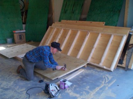 |
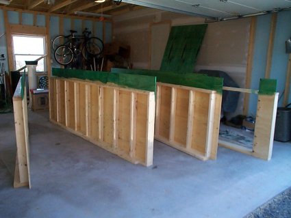
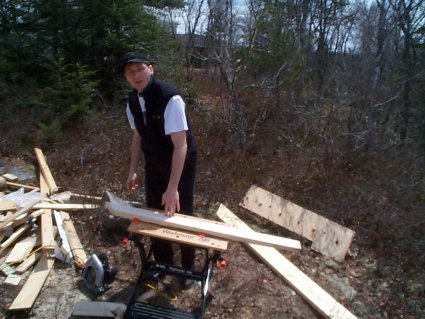
April 12 to 16, 2003: My dad hard at work on the walls which were pre-fabricated in the garage. You can also see the 3/4" plywood for the floor in the background - one side has been treated with wood preservative. |
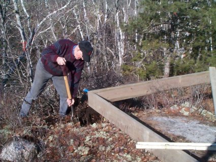 |
April 14: My dad again hard at work. We built the outside frame of the floor and used it to position the concrete posts for the building on the ridge. The bedrock was exposed (very near or at the surface!) and holes were drilled with an industrial hammer drill. Rock anchors and threaded rod were used to firmly attach the concrete posts to the bedrock. |
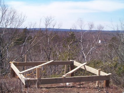 |
April 14: All four forms were carefully placed and filled with concrete and rock (readily available all over the back yard!). Anchor bolts were also inserted into the concrete and held in place with duck tape - what else! This view gives you an idea of what the western horizon looks like - there are still more trees to come down though. |
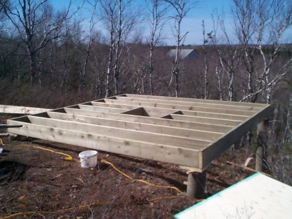 |
April 16: The 2x10 floor was completed and levelled on the concrete posts. The square hole is for the mount pier which will be added later after an appropriate height is determined. |
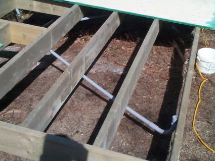 |
April 18: Four conduits were installed under the floor to feed wires from the centre of the observatory to four wall locations. |
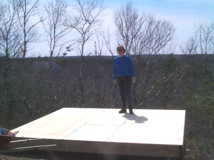 |
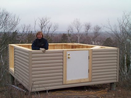
April 18: Michelle is standing on the finished observatory floor. |
 |
April 18: Here all four walls are ready for installation. The parts that will be near the ground have been painted with wood preservative. |
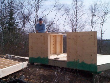 |
April 18: Two walls have been installed. They are bolted to the floor with lag bolts. |
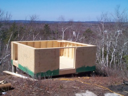 |
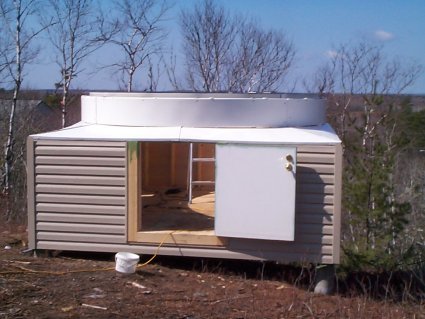
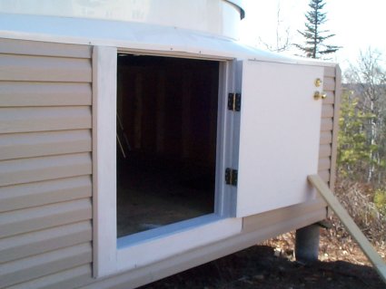
April 19: The four walls are now finished and the door frames were started. The front door is the main entrance. The back left door is intended to be used to roll out my 18" dob onto a future deck which will likely wrap around the left, back, and right of the observatory. |
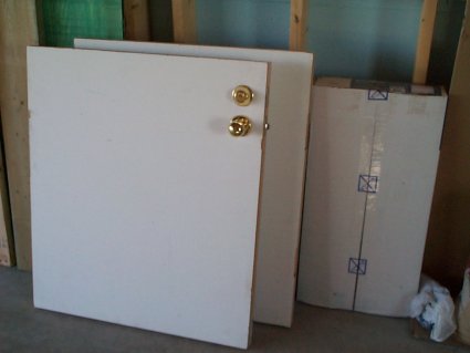 |
April 19: The doors are also ready for installation (thanks to Michelle's father). The two doors were made by sawing one solid wood fire door in half. |
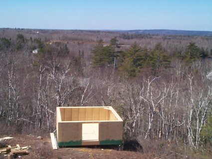 |
April 19: Here is a wider view taken from my 2nd floor home office window. In the background, you can see the hills that rise above St. Margaret's Bay (a few kilometres away), a glimpse of highway 103 below that, and my only troublesome streetlight below that :-(. |
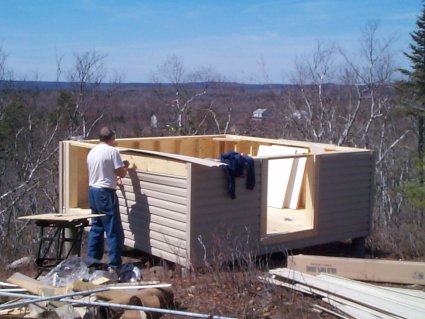 |
April 21: Today's main project was to install the siding, which matches the house in both colour and style. Before doing that, the door frames were finished. Shown hard at work is Michelle's father. My father also cut down a couple more trees today, clearing the southern horizon a bit better. |
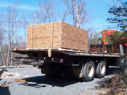 |
April 21: In early afternoon, what was described by the Home-Dome folks as "the box that ate the garage," finally arrived! It measured 7.5 x 6 x 4 feet and weighed 935 pounds! It was shipped from Maryland on April 7 and arrived in Dartmouth on April 10! It took 11 more days to get it moved the last 30 km! |
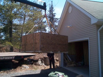 |
April 21: The usual process in shipping such large items is "loading dock to loading dock" and I don't have a loading dock! An arrangement had to be made with a specialty trucking company that could lower such a heavy box to the ground. |
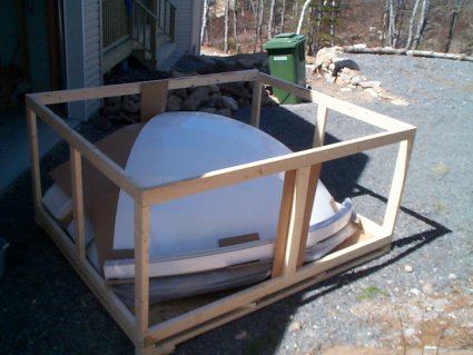 |
April 21: Once the box was opened, I was pleased to find all the parts very well packed and in good condition. |
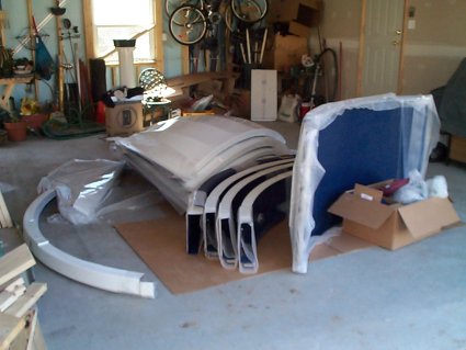 |
April 21: Shown are all of the dome parts laid out on the garage floor. The dome quadrants are just above centre. The shutter sections are on the right. The base ring is made of those four curved sections near the centre. Now I have to do that thing that guys rarely do before proceeding: READ THE ASSEMBLY MANUAL. |
 |
April 21: After the excitement of the dome finally arriving was over, there was still work to do. We had to finish the siding and Michelle's father installed the front door. |
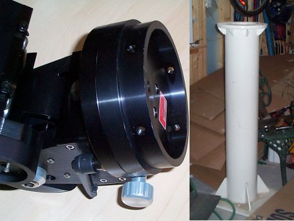 |
April 22: I didn't have much time this evening but I did manage to sketch up a drawing that Jim Crombie can use to design an adaptor that will mate the Titan mount base (left) to this massive 4 foot high steel pier (right) that I was able to acquire. |
 |
April 23-24: The weather deteriorated for a couple of days, so I decided to start setting up the dome on the garage and becoming familiar with the various bits and pieces. |
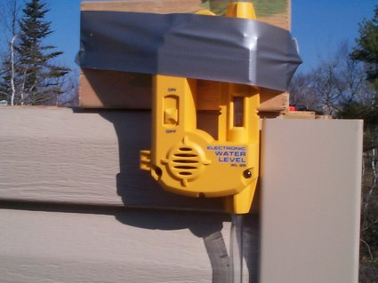 |
April 26: The day started off with accurately levelling the building using a neat gadget called a water level loaned to me by Darryl at the nearby Prospect Observatory. |
 |
April 26: About mid-morning Craig Levine arrived to help and we began working on the supports for the dome. |
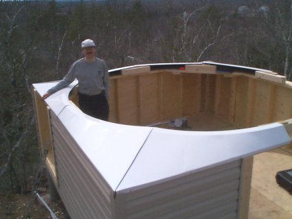 |
April 26: The eight segments of the skirt, which transition from a square building to the round dome, fit perfectly. Under the skirt you can see some of the support blocks that the dome bolts to. |
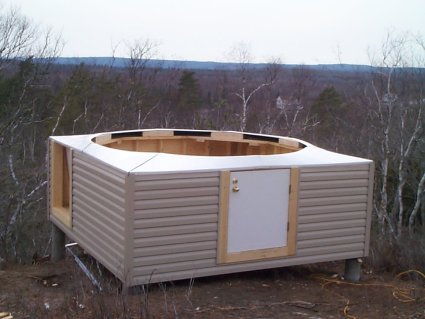 |
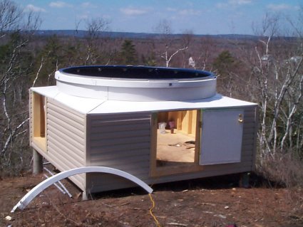
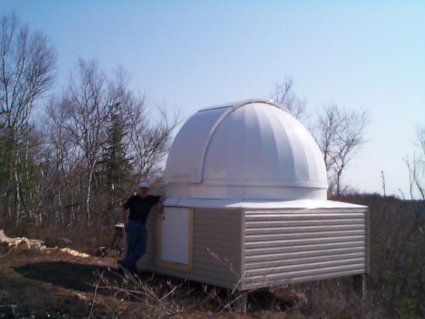
April 26: By late Saturday afternoon the skirt was finished. One more good days work (not Sunday, because its pouring rain) should see the dome installed! |
 |
April 28: The day began with the installation and bolting together of the four sections of the dome base ring. They were then adjusted to form a near circle over the centre of the skirt. |
 |
April 28: My Dad arrived about mid-morning and again using the water level, the dome was carefully levelled (using washers as spacers) and bolted to 2x4 supports located at eight places around the circumference. |
 |
April 28: Installing the four sections (one is shown leaning against the building) of the dome support ring was next. This is the ring that rests on the wheels the dome rotates on and supports the weight of the dome. |
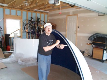 |
April 28: Bolting the dome quadrants together in the garage was easy. We then had to install two PVC tracks that would later be used for the electric shutter mechanism - this proved be more tricky to figure out (no wonder they include a CD full of images showing how to install the electric shutter!). |
 |
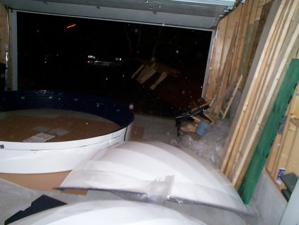
April 28: After the two dome halves were ready, we had to carry them from the garage to the backyard over the boulder strewn landscape. These were much heavier than we expected them to be! |
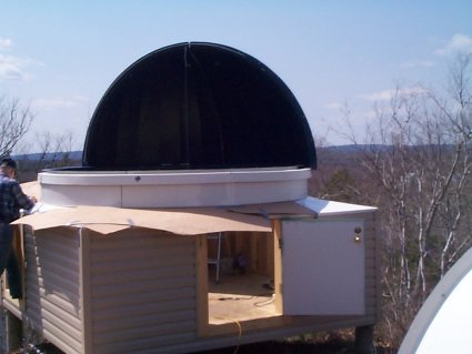 |
April 28: Lifting the dome halves from ground level up onto the dome support ring was the most difficult task of the day. Cardboard was duck-taped to the skirt to protect it from getting damaged. I wish I could have taken pictures of the contortions necessary to get those suckers up there! The gusty wind didn't help matters. |
 |
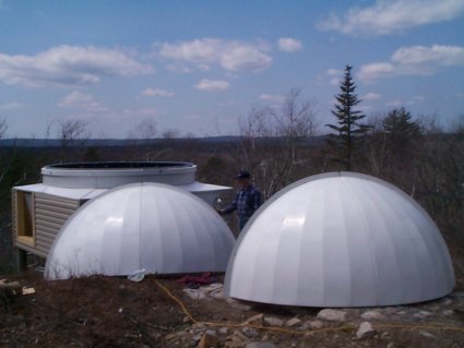
April 28: Both dome halves have now been raised and bolted to the dome support ring and the dome now rotates! |
 |
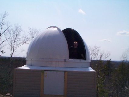
April 28: The day ended with the addition of the dome shutters and the shutter restraint system (these stop the shutters from blowing off!). There is still a great deal of work left to do, but clearly today's work completed a major milestone that I couldn't have done without my Dad's help. |
 |
May 3: Saturday started out wet, but not too wet to work inside installing the two dome rotation motors, its power supply, and wiring. These gear-motors are very noisy, but seem to work very well. Hopefully they won't wake up the neighbours! |
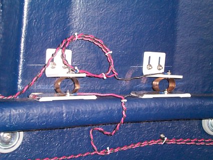 |
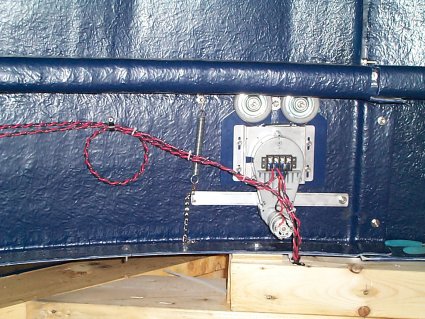
May 3: After the rotation motors were finished, I installed the electric shutter system. This system is quite complex, with two steel cables, a gear motor and travelling nut, several pulleys, spring tensioner, etc. They even include a CD full of pictures showing you step by step how to install it! The picture at left shows the contacts used to get power from the fixed part of the dome to the rotating part. You can see more of the mechanism in the background three pictures below. By end-of-day the system basically worked, but I was still adjusting the cables two days later. |
 |
May 4: Sunday was a busy day. Too many little things were done to mention or show in pictures. The biggest job completed was the caulking of all the joints in the dome with silicon sealant. I still have silicone on my fingers 2 days later as I write this! I also primed the front door and frame (I hate painting!) |
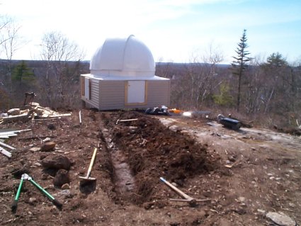 |
May 4: Dad also took it upon himself (it's true, ask Michelle!) to start digging the trench for the conduits that will provide AC power, internet, USB, phone, speakers, security, and telescope control from the house. Can you tell that we will be well equiped out there??!!! To his surprise, there was actually some ground to dig - we expected to hit a lot of bedrock. |
 |
May 5: Finally a clear night arrived when I wasn't exhaused from building all day, so I decided it was time for "first-light." In early evening I lugged all the equipment outside and set it up for the first time. I think it took about 7 trips! The mount is just on its tripod, since I want to experiment with its height before committing to a fixed pier height. |
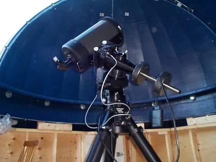 |
May 5: The first object looked at was the crescent Moon, then Jupiter. The images were, thankfully, ok (Michelle was impressed). I was very much in a learning curve with the Gemini mount controller since this was my first time using it. My initial reaction is that this mount is really smooth and solid. There was no backlash observed whatsoever when reversing directions in either RA or Dec. For the next two hours I used the mount's polar alignment assist feature, but I gave up in frustration - I need my Telrad! |
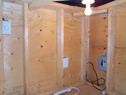 |
May 10: Today was too wet outside to continue trim and door painting, so I started and finished the power and light wiring instead. Shown is the corner where main switch/fuse box is located. I installed 6 AC outlets, including one at the centre of the floor. I also installed four lights (in the the low corner areas) controlled by a dimmer switch. Two of them also have "pull cord" on/off switches. After I get some red paint, I'll install red bulbs in at least the non-switched locations. |
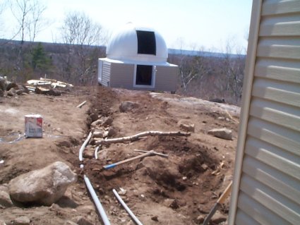 |
May 17: It was finally time to install and begin to bury the electrical conduits between the observatory and the house. The smaller conduit contains a 12-gauge 15A 120VAC line and the larger one contains three CAT5 cables (ethernet, PC USB extender, and security/misc), one CAT3 cable (phone), and a speaker wire for the stereo. They are separated by about 8 inches in the ground to reduce the chance of interference. |
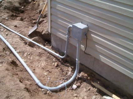 |
May 17: The conduits enter the house through a junction box which feeds the wires into the basement though a conduit that I had installed by the electrician when the house was built last summer (see, I was thinking ahead!). |
 |
May 18: Today was a day of many small jobs. Among other things, I wired the 120 VAC power into the house, wired the house-end of the phone line, planed the door so it fit better, and put another coat of trim on the doors and their frames. I also took apart the mount and tested the new steel pier adaptor that Jim Crombie designed and had machined (it fits!). |
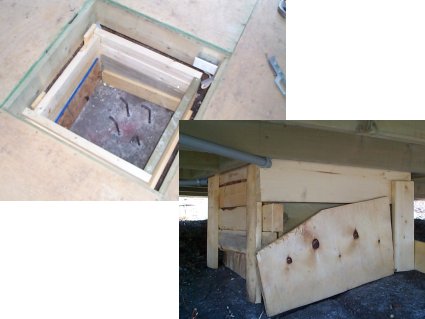 |
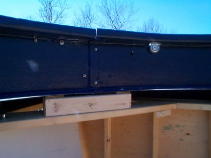
May 19: Today was the day Dad and I put in the concrete base for the pier. The photo at upper left shows the completed wooden form with four concrete bolts anchored into the bedrock. At lower right you can see the form as viewed from beneath the floor. |
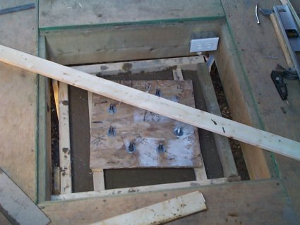 |
May 19: Here we see the completed concrete base. I polar-aligned the mount a couple of nights earlier and later marked the approximate north-south line on the floor. I then made a wooden template of the steel pier and positioned/leveled it carefully in the setting concrete to ensure that the bolts would fit properly. |
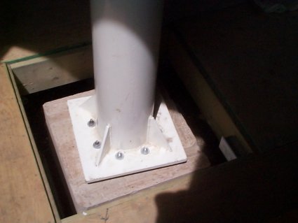 |
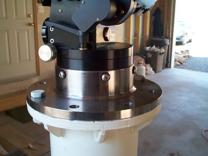
May 24: Saturday arrived and it was finally time to install the steel pier. The bolts in the concrete fit the pier perfectly and it wasn't difficult to get it reasonably level. During the week I had been putting coats of paint on the pier adapter and doing other small jobs, such as hooking up the phone and the internet cables to the house - yes, we are now wired! |
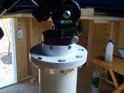 |
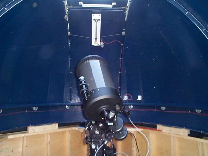
May 24: Next, the pier adapter, the mount and the scope were installed. From what I can tell, this pier is rock-solid. |
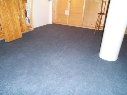 |
May 26: Home-Sweet-Home - the indoor-outdoor carpet was installed tonight. Only problem is - now I have to take off my shoes when entering the observatory! All that's left to be done before being fully operational with "phase one" is the pier wiring, to wait for the replacement telescope electronics to arrive from Losmandy (I think my 12V power supply has been blowing up the Gemini controllers), and of course to wait for some clear skies. |
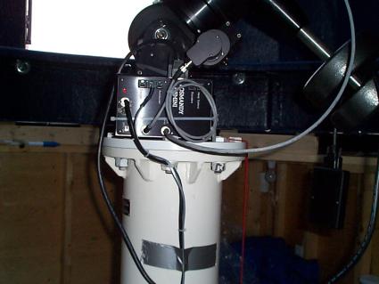 |
June 2: FIRST LIGHT NIGHT: The replacement Gemini controller and the new power supply arrived today and so did some clear skies! Before dark I installed it and all the needed wiring - duct tape and all - for the night. |
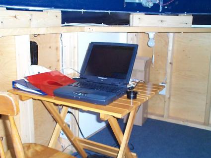 |
June 2: I also setup the laptop so I could test out the Gemini's serial interface. After dark the first task, after verifying that the mount was working properly (it was), was to polar align the mount for the first time. The Gemini has two modes that help you polar align the scope (it has no polar scope). The first mode has you repeatedly moving the scope back and forth between a star near the east or western horizon and one near the meridian and making adjustments to the mount each time - this gets you within one degree of the pole. The second mode has you align the mount on several stars after which it knows how far you are from the pole and it assists you in making the final adjustment. |
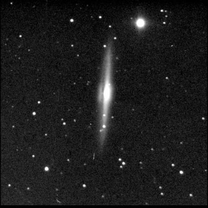 |
June 2: Since my initial tests were going so well, I decided to set up the ST9 CCD camera. Before I installed the camera, watched the mount's tracking with a reticle eyepiece and then roughly trained its periodic error correction (PEC) function. I focused the camera using a star in Virgo. I then imaged this nearby (in the sky, but in space its about 75-million light years away!) edge-on spiral galaxy named NGC 5746. In this 3.5-minute exposure, the faintest stars recorded are about 20th magnitute! |
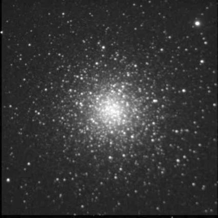 |
June 2: The second target was the globular cluster M3. The mount slewed about 30 degrees to M3 and put it dead centre of the CCD frame. This is a 5-minute exposure (10 x 30s combined).
|
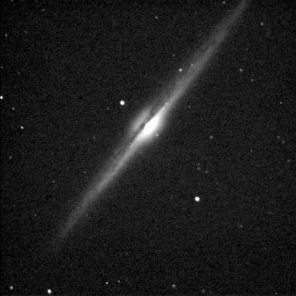 |
June 2: The last target before the clouds moved in was the well-known edge-on spiral galaxy NGC 4565 in Coma Berenices. This is about a 2-minute image taken through thin clouds. |
Last Updated: June 3, 2003